Description
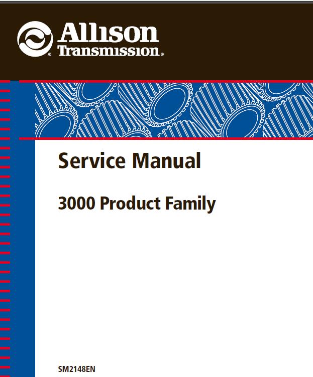
Allison 3000 Series Transmission Service Repair Manual Download
Make: Allison
Pages: 217
Format: PDF
Size: 19.6mb
Language: English
Requirements: Adobe PDF Reader & WinZip
Compatibility: All Versions of Windows & Mac/IPAD
Covers: Allison Transmission 3000 Series Vocational Models
- Highway Series 3000 HS
- Rugged Duty Series 3000 RDS, 3500 RDS
- Emergency Vehicle Series 3000 EVS, 3500 EVS
- Motorhome Series 3000 MH
- Truck Recreational Vehicle Series 3000 TRV, 3200 TRV
- Pupil Transportation/Shuttle Series 3000 PTS
- Specialty Series 3200 SP, 3500 SP, 3700 SP
- Bus Urban Series B 300, B 400
- T 200 Series T 250/T 255/T 260/T 265/T 270/T 280
- T 300 Series T 310/T 325/T 350
The 3000 Series Service Manual describes overhaul procedures for Allison 3000 Product Family automatic transmissions. Please see the Troubleshooting Manual for diagnostics & wiring diagrams.
- The major transmission components are described and their functions explained
- Detailed instructions are provided for disassembly, rebuild, and re-assembly
- Part inspection instructions
- Wear limits and spring data
Topics in the Allison 3000 Series Transmission Service Repair Manual:
Section 1. GENERAL INFORMATION
1–1. SCOPE OF MANUAL
a. Content and Organization
b. Illustrations
c. Maintenance Information
1–2. SUPPLEMENTARY INFORMATION
1–3. ORDERING PARTS
1–4. GENERAL DESCRIPTION
a. Major Modules
b. Unique Features
1–5. MAJOR MODULES
a. Input Module .
b. Torque Converter
c. Power Takeoff Provision
d. Main Housing and Gear Module
e. Range Clutches
f. Gearing Ratios
g. Control System and Electronic
Control Unit (ECU)
h. Oil Filters
i. Transmission Fluid Coolers
j. Output Configuration
1–6. MODEL DESIGNATION CODE
a. 3000 Product Family Vocational Model Standard and Optional Features
1–7. DIAGNOSIS
a. Before Starting .
b. DO NOT SHIFT or CHECK TRANS Light
c. Entering Diagnostic Mode
d. Diagnostic Codes
e. Displaying Diagnostic Codes
f. Diagnostic Code Displays
g. Exiting Diagnostic Mode
1–8. PRESERVATION AND STORAGE
a. Storage
b. Preservation Methods
c. One Year Storage (Without Fluid)
d. One Year Storage (With Fluid).
1–9. RESTORING TRANSMISSION TO SERVICE
a. Transmission Exterior.
b. Sealed Breather and Openings
c. New Transmissions.
d. Stored Without Fluid
e. Stored With Fluid
1–10. OPERATING INSTRUCTIONS
1–11. SPECIFICATIONS AND DATA
1–12. ELECTROMAGNETIC/RADIO FREQUENCY INTERFERENCE
Section 2. PREVENTIVE MAINTENANCE
2–1. SCOPE
2–2. PERIODIC INSPECTION AND CARE
a. Exterior Cleaning and Inspection
2–3. IMPORTANCE OF PROPER FLUID LEVEL
a. Transmission Fluid
b. Oil Level Sensor
c. Electronic Controls and Protection Circuits
2–4. ELECTRONIC FLUID LEVEL CHECK
(WHEN AN OPTIONAL OLS IS PRESENT—FULL-FUNCTION PUSHBUTTON OR LEVER SHIFT SELECTORS)
a. Fluid Level Check Procedure
2–5. ELECTRONIC FLUID LEVEL CHECK (WHEN AN OPTIONAL OLS IS PRESENT—STRIP TYPE PUSHBUTTON SHIFT SELECTORS)
a. Fluid Level Check Procedure (WTEC II)
b. Fluid Level Check Procedure (WTEC III)
2–6. MANUAL FLUID LEVEL
CHECK PROCEDURE
a. Preparation
b. Consistency of Reading
2–7. COLD CHECK
a. Purpose
b. Cold Check Procedure
2–8. HOT CHECK
a. Procedure
2–9. KEEPING FLUID CLEAN
a. Foreign Material.
2–10. FLUID RECOMMENDATIONS
2–11. FLUID AND FILTER CHANGE INTERVAL
a. Fluid and Filter Changes
b. Fluid Analysis.
2–12. FLUID CONTAMINATION
a. Water.
b. Engine Coolant
c. Metal. .
2–13. FLUID AND FILTER
CHANGE PROCEDURE
a. Drain Fluid
b. Replace Filters—3000 Product Family
c. Replace Filters—3700 SP or MD 3070PT
d. Refill Transmission
2–14. BREATHER
a. Location and Purpose
b. Maintenance
2–15. CHECKING CLUTCH PRESSURES
a. Transmission and Vehicle Preparation
b. Recording Data
c. Comparing Recorded Data
to Specifications
d. Pressure Specifications for all 3000 Product Family Transmissions
2–16. TRANSMISSION STALL TEST AND NEUTRAL COOL-DOWN CHECK
a. Purpose
b. Stall Testing Preparation
c. Performing a Transmission Stall Test
d. Driving Transmission Stall Test
e. Driving Transmission Stall Testing Preparation
f. Performing a Driving Transmission Stall Test
g. Neutral Cool-Down Check Procedure
h. Transmission Stall Test Results
2–17. FLUID LEAK DIAGNOSIS
a. Finding the Leak
b. Powder Method
c. Black Light and Dye Method
d. Possible Points of Fluid Leaks and Their Causes
e. Repairing the Leak
2–18. OUTPUT FLANGE/YOKE AND OIL SEAL MAINTENANCE (All, Except 3700 SP and MD 3070PT)
a. Disassembly
b. Assembly
2–19. YOKE AND OIL SEAL MAINTENANCE (3700 SP and MD 3070PT)
a. Disassembly
b. Assembly .
2–20. ON-VEHICLE MAINTENANCE
Section 3. GENERAL OVERHAUL INFORMATION
3–1. SCOPE
3–2. TOOLS AND EQUIPMENT
a. Improvised Tools and Equipment
b. Special Tools
c. Mechanic’s Tools and Shop Equipment
3–3. REPLACEMENT PARTS
a. Ordering Information
b. Parts Normally Replaced at Overhaul
3–4. CAREFUL HANDLING
3–5. CLEANING AND INSPECTION
a. Dirt Causes Malfunction
b. Cleaning Parts
c. Cleaning Bearings
d. Keeping Bearings Clean
e. Inspecting Bearings
f. Inspecting Cast Parts and Machined Surfaces
g. Inspecting Bushings and Thrust Washers
h. Inspecting Sealrings and Gaskets
i. Inspecting Gears
j. Inspecting Splined Parts
k. Inspecting Threaded Parts
l. Inspecting Retaining Rings
m. Inspecting Springs
n. Inspecting Clutch Plates
o. Inspecting Swaged and Interference-Fit Parts
p. Inspecting Retainer and Ball Assembly in Retarder Stator
q. Inspecting Sealing Surfaces
3–6. ASSEMBLY PROCEDURES
a. Parts Lubrication
b. Grease Used for Assembly
c. Sealing Compounds and Nonsoluble Greases
d. Clutches and Pistons
e. Threaded Plugs and Hydraulic Fittings
f. Coated Threaded Fasteners
g. Lip-Type Seals
h. Butt-Joint Sealrings
i. Bearings
j. Electrical Components
3–7. REMOVING (OR INSTALLING) TRANSMISSION
4–2. DISASSEMBLY OF TRANSMISSION
Section 5. MODULE REBUILD
5–1. SCOPE
5–2. GENERAL INFORMATION FOR MODULE REBUILD
5–3. TORQUE CONVERTER MODULE
5–4. TORQUE CONVERTER HOUSING MODULE (Models Without PTO Provision)
5–5. TORQUE CONVERTER HOUSING MODULE (Models With PTO Provision)
5–6. FRONT SUPPORT AND CHARGING OIL PUMP MODULE
5–7. ROTATING CLUTCH MODULE
5–8. C3/C4 AND MAIN HOUSING MODULE
5–9. MAIN SHAFT MODULE
5–10. P1 PLANETARY MODULE
5–11. P2 PLANETARY MODULE
5–12. RETARDER MODULE
5–13. REAR COVER MODULE
5–14. ADAPTER HOUSING AND P3 OVERHAUL
5–15. SCAVENGE PUMP OVERHAUL
5–16. TRANSFER CASE MODULE
5–17. CONTROL VALVE MODULE
Section 6. TRANSMISSION ASSEMBLY
6–1. SCOPE
6–2. ASSEMBLY OF TRANSMISSION
Section 7. WEAR LIMITS AND SPRING DATA
7–1. WEAR LIMITS DATA
a. Maximum Variations
b. Cleaning and Inspection
7–2. SPRING DATA
a. Spring Replacement
b. Inspection

Walter Kirkwood –
“Received in timely fashion. Works well.”